Orthophoto to CAD: from photogrammetric output to DXF
Orthophotos are metrically correct but still raster. This is the workflow for survey offices that need consistent measurements across the whole surface.
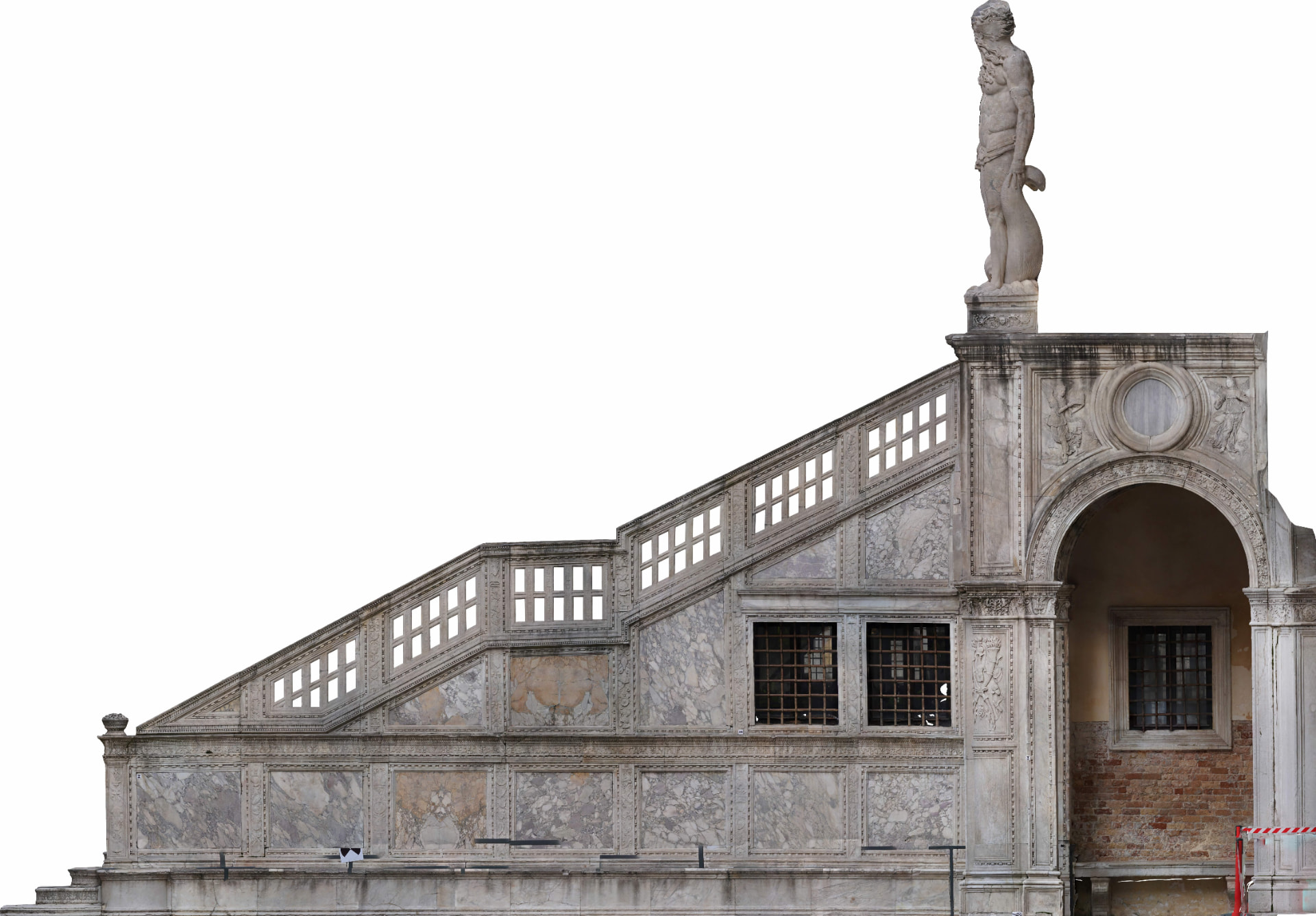
Drag the divider to compare the source image with the generated vector drawing (SVG / DXF).
A different user: the survey office
Readers of this page have already done the metric work: a photogrammetric campaign, a laser scan, a rectification in Metashape, RealityCapture, PhotoModeler or an equivalent pipeline. The deliverable in hand is an orthophoto or rectified photoplan — a raster with constant scale and perspective removed. What remains is the step that dominates the budget: turning that raster into CAD geometry.
Compared with the single-photograph route, the accuracy regime changes entirely. On a rectified source, two-point calibration no longer interprets perspective; it only fixes the scale factor. Measurements stay consistent in every direction and across the full extent of the surface — the condition heritage and infrastructure specifications require when a drawing must be spot-checked.
What gets extracted on large elevations
The engine vectorises opening outlines, mortar courses and joints, springing lines, jambs and lintels, stone elements, cornices and string courses, together with losses, detachments and structural cracks. On frescoed or mosaic surfaces it follows the boundaries of colour fields and of the larger tesserae. The output is a base drawing for as-built elevations, thematic decay mapping and surface quantity take-off.
Orthophotos are usually heavy files, and the input accepts JPG, PNG and WebP up to 40 MB. In practice, export at the lowest resolution that still resolves the detail you intend to vectorise: the ratio between pixel size and real size determines how fine the extracted paths can be.
Spatial coordinates and georeferenced insertion
Before generation you can declare the drawing's spatial coordinates: insertion X, Y and Z, real width and height, rotation, and origin at the lower-left corner or at the centre. The DXF therefore lands directly in the project or GIS coordinate system, with no manual repositioning to introduce error.
The DXF imports into AutoCAD, BricsCAD, Rhino, QGIS and QField, where it can be overlaid on point clouds, laser-scanner sections and existing survey layers. The SVG covers layout, presentation plates and attachments for authorisation procedures.
Limits: which orthophotos give poor results
A photoplan is not automatically a good source. Orthophoto mosaics produced by photogrammetric software often show visible seams between frames, with jumps in tone and sharpness: along a seam the engine may read the tonal step as a geometric line. Export radiometrically balanced mosaics, or accept that those lines will have to be deleted in CAD.
Deep shadow areas and portions reconstructed from few frames carry insufficient detail: the tracing comes out patchy exactly where the survey itself is weakest. The same holds for heavily weathered, homogeneous surfaces — washed-out render, fully repointed masonry — where the joint is invisible even to the eye: if the edge is not in the raster, it cannot appear in the vector.
One practical limit is file weight: 40 MB per image. A large elevation exported at full resolution easily exceeds that, and the right answer is not to compress the whole elevation but to split it into coherent portions (by bay, by storey) and convert them separately, giving each its own spatial coordinates so they reassemble in alignment in CAD.
Compared with manual vectorisation: real timings
Manual vectorisation of a photoplan is the most expensive item in the deliverable. A moderately complex historic elevation — openings, cornices, string courses, mortar coursing to be represented — generally takes an experienced technician one to two working days, and on frescoed surfaces or irregular coursed masonry, where the tracing follows thousands of edges, it easily runs to several days.
With CVCAD the same portion is vectorised in minutes and returns a DXF already in scale and, if requested, already placed in the reference system. The remaining work is editing: removing spurious paths along seams, closing polylines, splitting into thematic layers. On the projects we follow this step typically costs a small fraction of the original time — a few hours instead of several days — and moves the technician's effort from tracing to interpretation.
Read the comparison correctly: metric accuracy is not the software's merit but the rectified source's. CVCAD preserves that scale and carries it into CAD; spot-check verification and sign-off remain a professional responsibility.
At a glance
- Input: rectified photoplans and photogrammetric orthophotos, JPG, PNG or WebP up to 40 MB
- Processing time: typically 60–120 seconds, around 90 on average; high-resolution photoplans can take longer
- Consistent measurements across the surface, not only along the calibration direction
- Optional spatial coordinates: X, Y, Z, real size, rotation, origin
- DXF ready for AutoCAD, BricsCAD, Rhino, QGIS and QField
- Base for as-built elevations, decay mapping and quantity take-off
Questions
What export resolution should I use for the orthophoto?
Start from real pixel size: if the finest detail you must vectorise is a few millimetres wide, you need two or three pixels across it. Exporting beyond that only increases file weight without adding usable geometry.
Can the drawing be overlaid on laser-scanner point clouds?
Yes. Setting insertion point, real size, rotation and origin in the spatial-coordinates section aligns the DXF with the cloud or with sections already in the project, with no manual repositioning.
Is it acceptable for specifications requiring verifiable deliverables?
On a rectified source, yes: the scale is declared, the file is a DXF of real entities, and the calibration measurement is documented. Spot-check verification and final validation stay with the professional signing the plate.
How do I handle an elevation larger than 40 MB?
Split it into coherent portions — by bay or by storey — and convert each separately, declaring its own spatial coordinates: the resulting DXF files reassemble in alignment in CAD with no manual repositioning.
Other conversions
What the process returns, and with what margins: nature and limits of the deliverable.
Try CVCAD on your next survey
Sign up and get 1 free conversion: upload a photo and download a DXF already in real millimetre scale.