How to convert an orthophoto to CAD: elevations and plans, step by step
The orthophoto has become the standard record of a building, yet clients, heritage officers and contractors still ask for a measured line drawing. This guide covers the whole route, from export in your photogrammetry software to a DXF ready for the drawing sheet, and shows where accuracy gets lost along the way.
Published · 2026-10-01
Orthophoto, orthomosaic, rectified photograph: what is the difference
The three terms are often used interchangeably, but they describe different products, and the difference matters once you move to CAD.
Rectified photograph (photoplan): one or more frames rectified onto a plane using at least four points of known coordinates. It removes perspective only for what lies on that plane: anything that projects from it, such as cornices, balconies and sills, stays displaced from its true position.
Orthophoto: an orthographic projection generated from the 3D model (mesh or elevation model). It also corrects the displacement caused by surface relief, which is why it has replaced planar rectification on articulated facades.
Orthomosaic: the name Metashape and drone mapping software give to an orthophoto assembled from many images. For drawing purposes it is an orthophoto.
Two properties matter for CAD conversion: constant scale across the whole image and no perspective. If the source lacks either, no vectorisation can recover it downstream.
orthophotocad.svg
Preparazione anteprima…
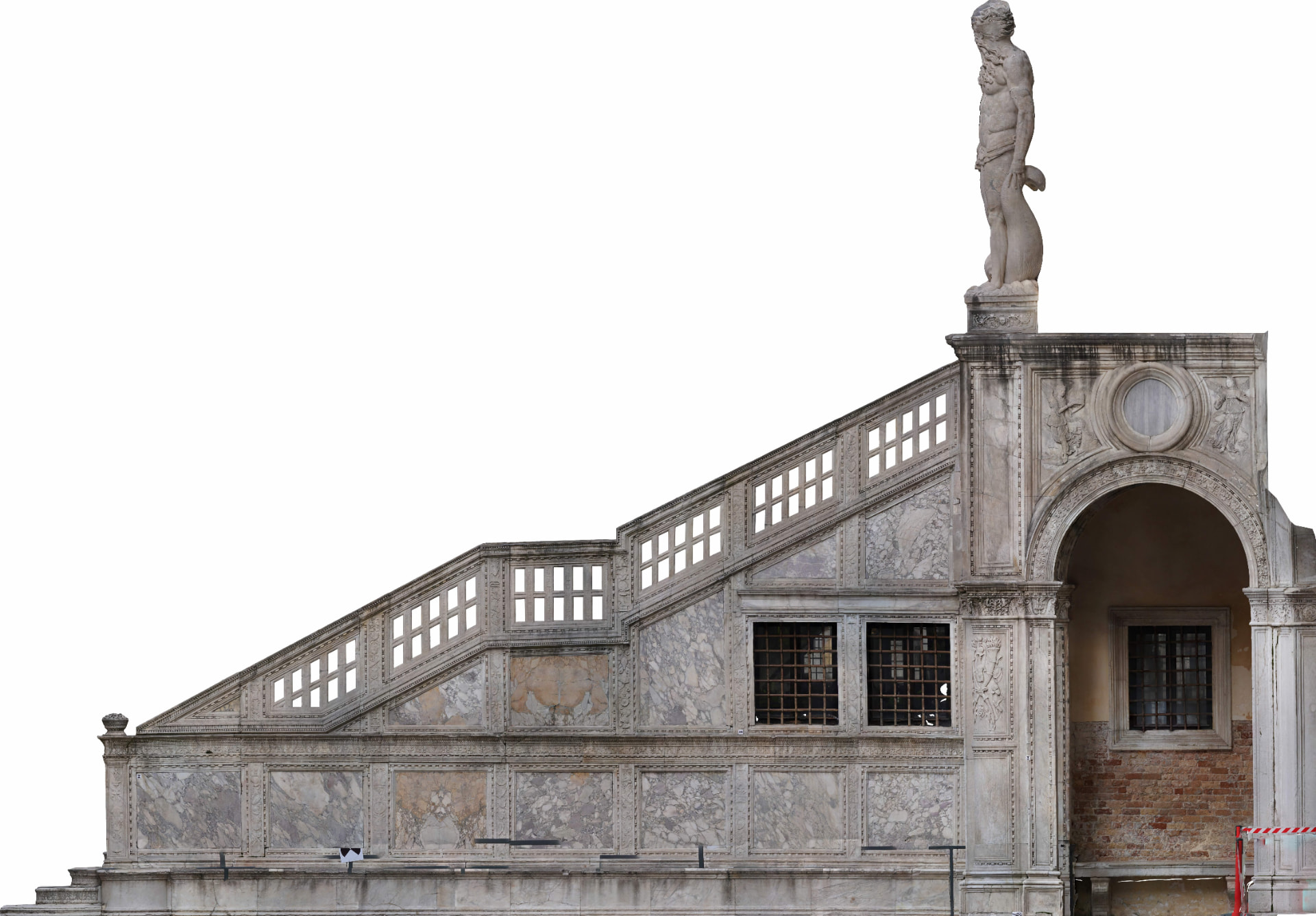
Drag the divider to compare the source image with the generated vector drawing (SVG / DXF / PDF).
Orthophoto of an elevation and the vector drawing generated by CVCAD.
Why tracing is still the bottleneck
The traditional route is familiar: attach the orthophoto in AutoCAD as a raster image, scale it from two points, lock the layer and trace every opening, cornice, stone and joint by hand. On a moderately complex historic elevation that means anything from a few hours to one or two working days, and it is usually the heaviest item in the survey fee.
Generic auto-trace tools, such as Illustrator's Image Trace or raster-to-vector converters, do not solve it. They follow pixel edges, not the architecture: stains, runs, patinas and shadows carry as much contrast as a mortar joint, and each becomes a line to delete.
Ways to draw from an orthophoto, compared
Method
Time per elevation
What you get
Main limit
Manual tracing in CAD
a few hours to 1–2 days
A clean drawing, already interpreted by the surveyor
Turnaround time and one more layer of interpretation
CVCAD
60–120 seconds per conversion, plus review
Polylines for openings, cornices, stones and joints, already in scale
A base to check and organise into layers, not a finished deliverable
From orthophoto to DXF, step by step
The procedure below works for facades, interior walls and floors. Only the plane you project the orthophoto onto changes.
Generate the orthophoto on the drawing plane
In Metashape, RealityScan (formerly RealityCapture) or 3DF Zephyr, project the model onto the plane of the facade, wall or floor, defined by markers or control points rather than by eye from the current view. A plane that is not parallel to the surface rotates the drawing or foreshortens one direction, and calibration cannot fix that later.
Export in a format CVCAD accepts
High-quality JPG, PNG or WebP, up to 40 MB per image. TIFF and GeoTIFF cannot be uploaded: keep the TIFF as the archive master and convert a copy. Note the pixel size (GSD) from the processing report, because you will need it for scale. More on keeping it intact: from orthophoto to DXF without losing scale.
Crop by bay, not by facade
Each conversion runs at a fixed resolution, so a tight crop gives every stone more pixels than a whole front does. Choose the crop size from your output scale, using the table in the next section. Cropping leaves the pixel size unchanged, resizing does not: to make the file lighter, crop.
Upload and convert
Upload the image in the app. If you want the DXF placed directly in your project or GIS coordinate system, fill in the spatial coordinates first: insertion point X, Y, Z, real width and height, rotation and origin. Conversion usually takes 60–120 seconds and returns openings, cornices, string courses, stones and joints as continuous polylines, discarding most of the contrast that carries no architectural meaning.
Set the scale
In the vector preview, pick two snap points and enter the real distance in millimetres, centimetres or metres. Use the longest readable base, between sharp ends such as crisp arrises, measured with a laser distance meter. If you know the GSD you can derive it from the pixels: real distance = GSD × pixels between the two points.
Download and check
Download the DXF (AutoCAD 2013 format) and the SVG. Before working on it, measure a second site distance on the drawing, along an axis different from the calibration one. If it deviates beyond the tolerance of your scale, the problem lies in the orthophoto, not in the calibration.
Finish the drawing in CAD
The DXF comes out without a layer structure: move the polylines onto the layers of your standard (openings, profiles, masonry), delete stray lines along mosaic seams and in deep shadow, close the polylines that need to become areas, then dimension and sheet the drawing at 1:50 or 1:20. For layer structure on thematic drawings: degradation mapping according to UNI 11182.
How much to fit in one conversion
The reference is plotting accuracy: by convention 0.2 mm on paper, which multiplied by the scale denominator gives the metric tolerance of the drawing. For reliable vectorisation, the orthophoto pixel should be no larger than half that tolerance.
Since each conversion works with about 4,000 usable pixels on the long side, your output scale also decides how much surface to fit in one image.
Scale, resolution and usable width per conversion
Scale
Plotting tolerance
Recommended pixel size (GSD)
Usable width per conversion
Good for
1:20
4 mm
up to 2 mm
about 8 m
One bay, a doorway, stone-by-stone drawing
1:50
10 mm
up to 5 mm
about 20 m
A whole mid-sized elevation with legible masonry
1:100
20 mm
up to 10 mm
about 40 m
Long frontages and overview sheets; fine joints are no longer legible
A second rule completes the table: the thinnest mark you want in the drawing, usually the mortar joint, must span at least two or three pixels. If it does not, it is not in the raster and cannot appear in the vector.
When a front is wider than the usable width, split it by bay or by storey and convert each portion separately. With its own spatial coordinates declared for each, the DXF files reassemble in alignment in CAD with no manual repositioning.
Elevations: what you get and what you do not
On an elevation the engine recognises openings, jambs, lintels and flat arches, cornices and string courses, pilasters, stone elements, individual stones and mortar courses, along with losses that have a readable edge.
It cannot return what the orthophoto does not contain. The soffit of a cornice and the side of a pilaster do not appear in a frontal projection; washed-out render or uniformly pointed masonry hides the joint even from the eye; areas in deep shadow or rebuilt from few frames produce patchy tracing.
If your source is a planar rectified photograph rather than an orthophoto, projecting elements are displaced in proportion to their projection and their distance from the camera axis: survey them separately or check them with direct measurements.
orthophotocad.svg
Preparazione anteprima…
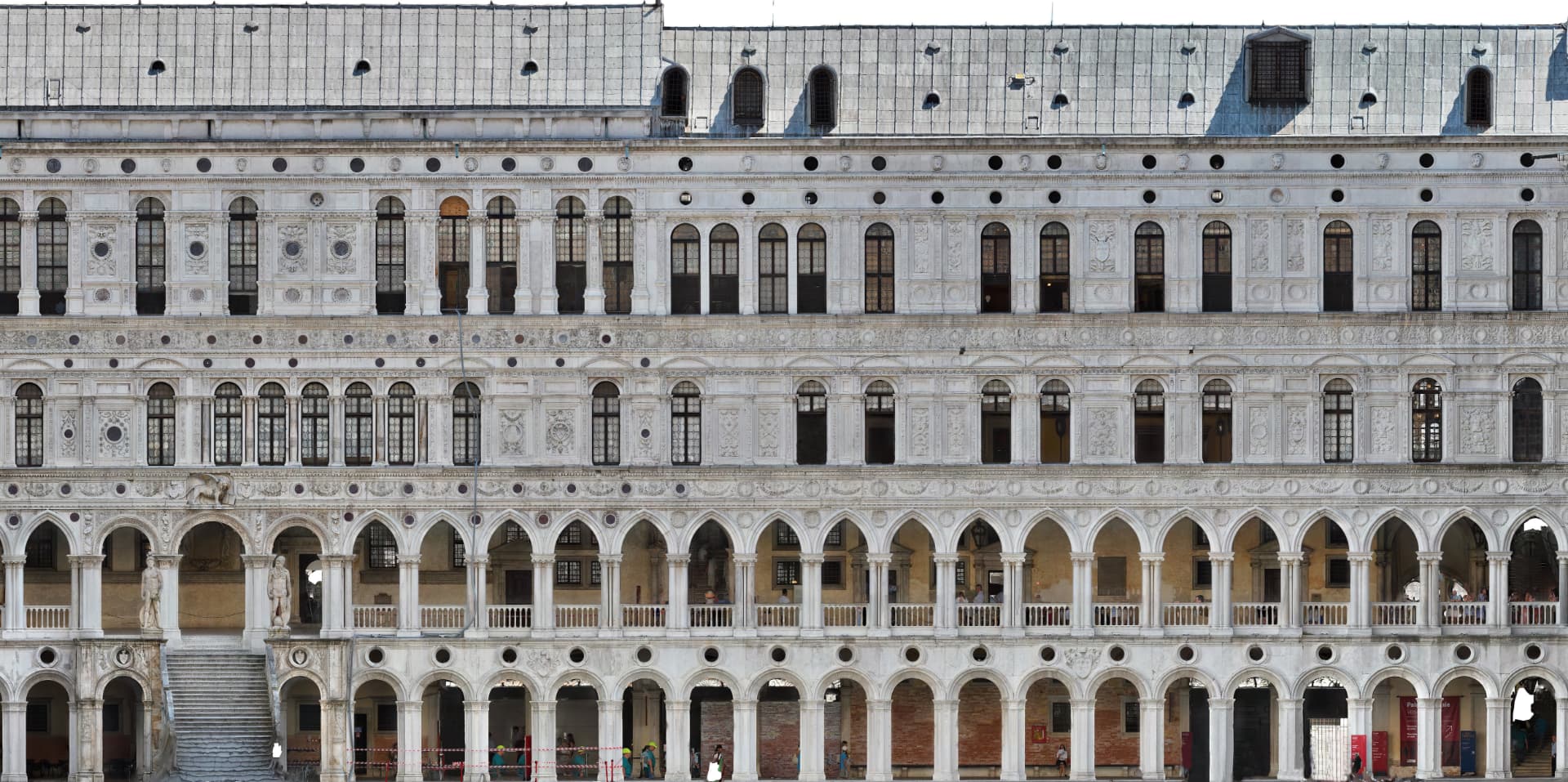
Drag the divider to compare the source image with the generated vector drawing (SVG / DXF / PDF).
Historic street elevation: source image and vector drawing.
Plans: floors, mosaics and vaults
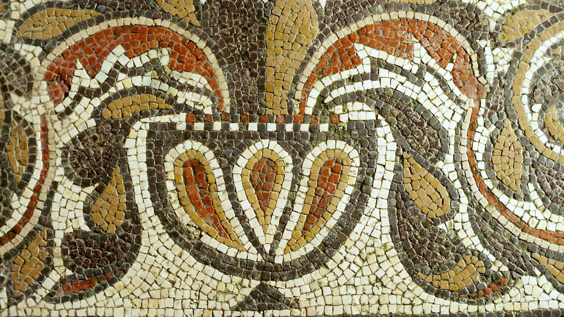
The same workflow works on the horizontal plane: a nadir orthophoto of a floor shot from a pole or a drone, an orthomosaic of an archaeological area, a roof plan. On a mosaic floor you get borders, fields and the larger tesserae; on a stone floor, the slab pattern and its joints.
Vaults need care. An orthophoto projected onto the horizontal plane gives the plan of the vault, useful for the geometric layout and for plotting ribs, groins and decoration. Areas measured on that plan are projected areas, though: where the vault curves, the real soffit area is larger than the one read on the drawing. To quantify cleaning or consolidation you need the developed surface or a correction for curvature.
orthophotocad.svg
Preparazione anteprima…
Drag the divider to compare the source image with the generated vector drawing (SVG / DXF / PDF).
Mosaic floor shot from above: fields and borders vectorised.
Where accuracy gets lost
Wrong projection plane. The one error no later step can correct.
Scale lost at export. A JPG exported without noting the GSD, or an image resized after export: the drawing becomes dimensionless or, worse, carries a false scale.
Orthomosaic seams. Tonal jumps between adjacent frames are read as lines: export radiometrically balanced mosaics or budget for clean-up.
Calibration on a short base. With 5 mm of uncertainty, the scale error is 0.5% over 1 m and 0.05% over 10 m.
Drawing units. When you import the DXF into your template, check that units match: a factor of 10 or 1,000 gives no warning.
No check. Verifying against a second real measurement is the only way to catch an upstream error.
A record drawing must show what is there, and nothing else
CVCAD produces the first draft of the drawing. Reviewing it against the orthophoto remains necessary: a ragged edge may have been tidied, an unclear detail misread. Metric verification and sign-off stay with the surveyor, as with any survey base. What the process returns, and with what margins: nature and limits of the deliverable.
What is the difference between an orthophoto, an orthomosaic and a rectified photograph?
A rectified photograph corrects perspective only for what lies on one plane. An orthophoto is an orthographic projection from the 3D model and also corrects projecting elements. Orthomosaic is the name many programs give to an orthophoto assembled from several images.
Can I use an ordinary photo instead of an orthophoto?
Yes, for a site visit or a quick base. On a perspective photo, though, scale is dependable mainly along the direction you calibrate. If the drawing must be verifiable across the whole surface, you need a rectified photograph or an orthophoto. The single-photo workflow is described in photo to CAD.
Does CVCAD accept TIFF or GeoTIFF files?
No: it accepts JPG, PNG and WebP up to 40 MB. Convert a copy of the TIFF and keep the original. Position in a coordinate system is declared through the spatial coordinates before conversion.
Can I get a DWG?
CVCAD exports DXF in AutoCAD 2013 format, which AutoCAD, BricsCAD, Rhino and QGIS open directly. If you need a DWG, open the DXF in AutoCAD and save it as DWG.
Is the DXF already split into layers?
No, the DXF currently has no thematic layer structure. Layering is done in CAD, to your office's or the specification's standard.
How accurate is the drawing?
Metric accuracy depends on the orthophoto: CVCAD preserves its scale and carries it into CAD. Always check the drawing against a second site measurement, along an axis different from the calibration one.
Does it draw every stone?
It depends on resolution and lighting. If the joint spans at least two or three pixels and is legible in the image, it generally does. On washed-out render, uniformly pointed masonry or deep shadow the joint is not visible and cannot be traced.
How do I handle a very long facade?
Split it by bay or by storey, convert each portion separately and declare spatial coordinates for each: the DXF files reassemble in alignment in CAD.
Try CVCAD on your next survey
Sign up and get 1 free conversion: upload a photo and download a DXF already in real millimetre scale.